


In this article we will discuss the proper steps to wire a solar panel array to a combiner box for use in a solar electric system. For safety reasons, great care must be taken to ensure no wires are energized until all wiring is completed. This means that at least one series connection in each string of solar panels be left open until all other wiring is completed. Wiring the solar panels is the last step in wiring a solar electric system, so make sure your transmission wires from the combiner box to the charge controller (off-grid system) or inverter (grid-tied system) are already connected before wiring the panels.
On the back of each panel there is either a Positive (+) and Negative (-) connection cable or a junction box with Positive (+) and Negative (-) connections indicated. Connection cables have solar industry standard water proof connectors, with the most common types being MC4, PV4, and T4. Junction boxes have terminals to connect user supplied wires. Connection cables or wire are used to connect panels to each other and to the combiner box, which is then wired to either a charge controller for off-grid systems, or an inverter for grid-tied systems. The combiner box is an outdoor rated enclosure, intended to be installed near the array, that serves as a junction point to tie together (combine) all wiring from the solar panels; Positive through breakers, and Negative through a negative bus bar. Strain relief wire fittings serve as wire pass-through-points for each pair of wires (Positive and Negative) into the combiner box. For this discussion we will assume the array consists of 6 solar panels in two parallel strings of three panels each. Each string will include Positive and Negative connection cables, a breaker and a strain relief wire fitting.
Before you begin wiring, verify the polarity of each panel by connecting a voltmeter to its outputs. Once polarity is confirmed, wire the “home run” leads in the combiner box. These are the wires that will connect to the Positive and Negative end of each series string of panels. If your panels have connection cables then you will use MC4 cables for this. MC4 cables are typically 30′-100’ long. One cable will be used for each string of modules. The cable has a male connector on one end and female on the other. The cable will be cut into 2 pieces so you will end up with one piece that matches the Positive output from your panels and one that matches the Negative. The cut ends will run into the combiner box. Before you cut the cable, confirm that the cable has enough length to comfortably reach the Positive and Negative leads from each string. Assuming your combiner box will be centrally located with respect to the layout of the panels, cut a single MC4 cable into two equal pieces. If your combiner box is off-center from the panels, cut the cable at appropriate lengths such as 10′ and 20′ or 8′ and 22′, etc. for a 30’ cable.
Inside the combiner box note that the breaker comb and the negative bus bar each host a large wire lug for connecting heavier gauge transmission wire to run power to your charge controller or inverter. Verify that those wires have already been connected properly before continuing. (Correct torque settings are also very important to be aware of when making all connections.) Now route the cut ends of the MC4 cable for the first string through the first strain relief. Strip approximately 1/4″ of insulation off each lead, and connect the Positive to the first breaker, and the Negative to the negative bus bar. Once connected, make sure the breaker is in the Off position. Repeat for the second leads using the second strain relief and breaker. Ensure that the breakers for each circuit are properly installed and stay in the Off position. Once connected, home run leads from the combiner box to the array may be set aside until ready to make the connection to each string’s leads.
A grounding conductor is required for PV arrays. This bonds all the panel frames together and to the rest of the system. As panels are installed to the racking be sure to attach ground lugs on each panel and run the grounding conductor from the PV array to the grounding lug in the combiner box. Some racking systems are designed to bond the panel frames to the racking automatically so only one grounding lug is required for the whole array. Make sure to read the racking installation manual to determine your system’s requirements.
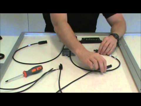
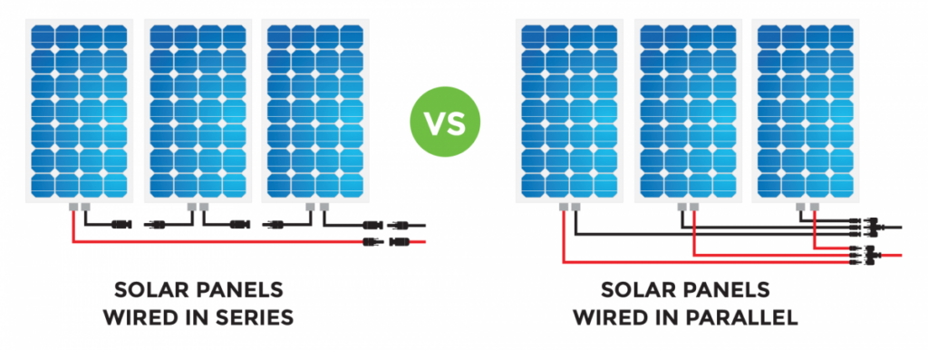
Time to move to the series connections of the first 3 panels. Plug a Positive (+) lead from one panel into the Negative (-) lead of a second panel. Then plug the Positive lead of the second panel into the Negative lead the third panel. There are now two series connections for this string. Repeat this step with the second set of three panels.
Now there are two series strings of three panels each. There is a Positive lead at one end of each string and a Negative lead at the other end. These are the leads that eventually get connected to the home run leads of the combiner box. Verify polarity again using a voltmeter to confirm which leads on each string are Positive and which leads are Negative. Reversing polarity may cause permanent damage and void manufacturer warranties on your product.
Once all other system installation and wiring is complete, the final connections to the array can be made. Verify that all breakers are off before connecting the string ends to the combiner box home runs. Once connected, do a final polarity check inside the combiner box. Each string can be tested with a voltmeter for proper polarity and voltage. The circuit breakers should be left in the off position until it is time to commission the system. Congratulations, the array has been safely wired and tested and is ready to provide power to your system.
With over 40 years of experience, Earthship Biotecture has the knowledge to help you with the correct system components for your solar electric system needs. Give us a call today at 575-751-0462 to speak with one of our engineers.